About us
More about our company
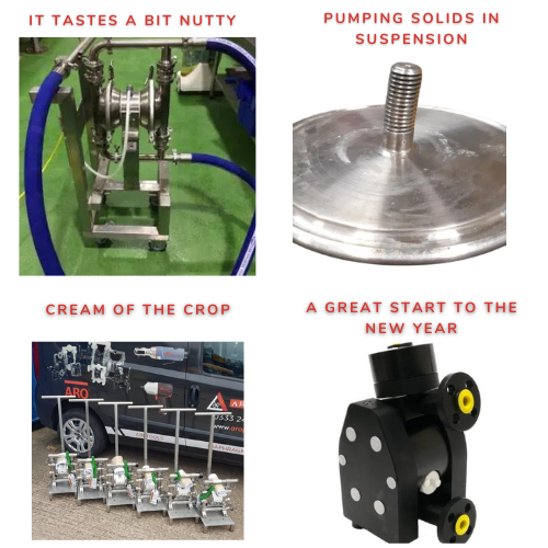
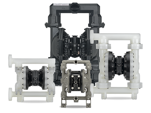
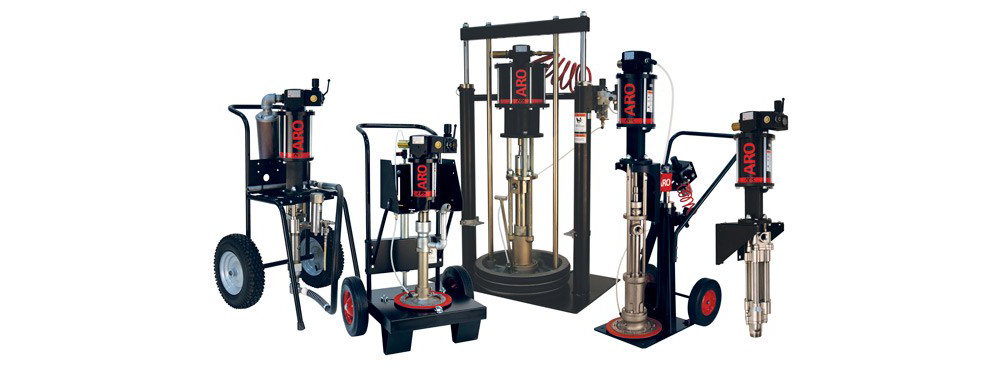
Case Studies
Our Case Studies show our capabilities and commitment to producing the best product


This calculator estimates pressure losses in suction and discharge pipework using well-established fluid-mechanics principles. Flow velocity is calculated from the entered flow rate and pipe diameter, after which the Reynolds number is determined to identify whether the flow is laminar or turbulent.
Laminar flow (Re < 2000)
Pressure loss is calculated using the Hagen–Poiseuille relationship, which accounts for viscous friction in smooth, low-velocity flow.
Turbulent flow (Re > 2000)
Pressure loss is estimated using the Darcy–Weisbach equation, with a typical friction factor value representative of clean, commercial pipework. This captures energy losses due to turbulence at higher flow velocities.
Static pressure effects from suction and discharge elevation are converted into bar using the fluid’s density (derived from specific gravity) and combined with the calculated frictional losses to provide the total suction pressure, discharge pressure, and differential pressure.
The results provided by this tool are estimates based on standard engineering equations and assumed pipe friction values. Actual system performance may differ due to factors such as pipe bends, fittings, valves, reducers, surface roughness, flexible hoses, pump inlet conditions, and installation layout. For critical applications, or where accuracy is essential, please consult Aroplus UK Ltd or Diaphragm Pumps Ltd for a full engineering assessment.
1. Flow & Velocity Calculations
Flow rate is converted from m³/h to m³/s, then used to calculate fluid velocity:
Velocity (V) = Flow Rate (Q) / Pipe Area (A)
Where:
Q = volumetric flow rate (m³/s)
A = π × (D/2)²
D = internal pipe diameter (m)
2. Fluid Properties
Fluid properties are derived from the user inputs:
Density (ρ) = Specific Gravity × 1000 (kg/m³)
Dynamic Viscosity (μ) = Viscosity (cP) / 1000 (Pa·s)
Assumes water-based fluids unless otherwise specified.
3. Reynolds Number
The Reynolds number determines whether flow is laminar or turbulent:
Re = (ρ × V × D) / μ
Flow regimes:
Laminar: Re < 2000
Turbulent: Re ≥ 2000
4. Laminar Pressure Loss (Hagen–Poiseuille Equation)
Used when the Reynolds number indicates laminar flow:
ΔP = (32 × μ × V × L) / D²
Where:
L = pipe length (m)
5. Turbulent Pressure Loss (Darcy–Weisbach Equation)
Used for most industrial diaphragm pump applications:
ΔP = f × (L / D) × (ρ × V² / 2)
Where:
f ≈ 0.02 (typical friction factor for clean commercial pipe)
Note: Actual friction factor may vary depending on pipe roughness, fittings, and flow conditions.
6. Static Head Pressure
Elevation changes in suction and discharge lines are converted to bar:
Static Pressure = (ρ × g × h) / 100,000
Where:
g = 9.81 m/s²
h = elevation head (m)
7. Total Calculated Pressures
The calculator provides:
Total Suction Pressure
Total Discharge Pressure
Total Differential Pressure
These combine friction losses and static head pressure for each pipe run.